LoRa MSG Assembly
As I learned that some people are trying to assemble the LoRa messenger I shared the other day, I decided to put together a post showing how to assemble it.
Step 1
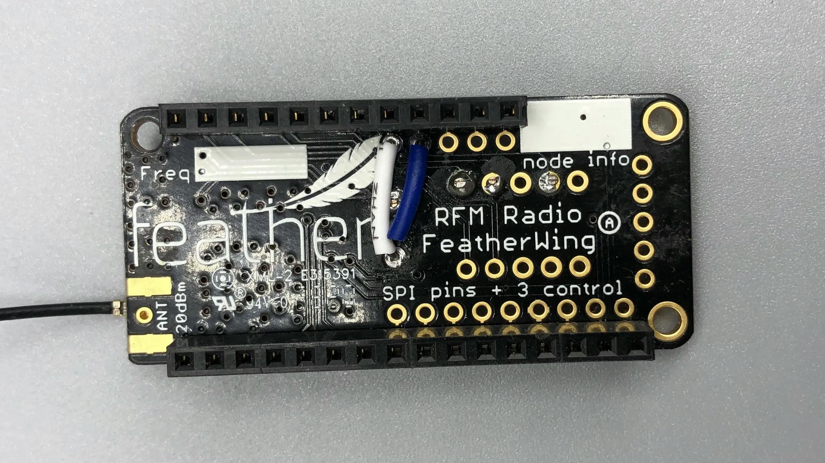
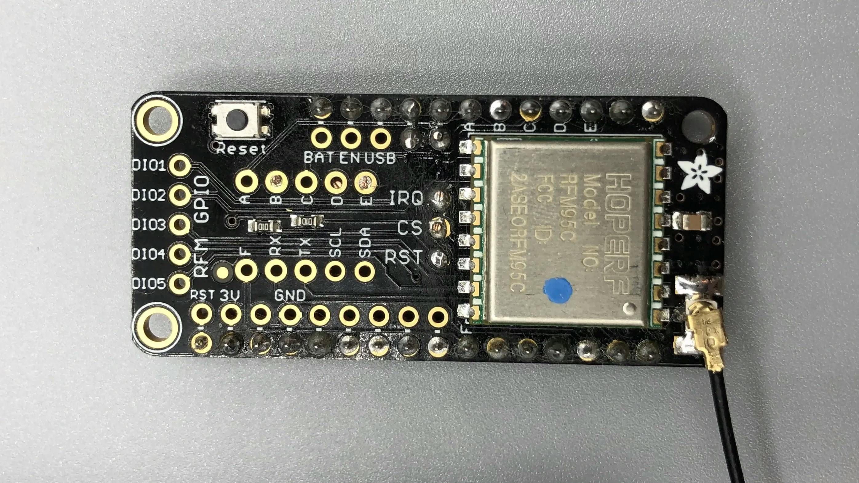
First we need to prepare the chips:
- Solder the short feather headers to the lora chip
- Solder the uFL antenna connector to the lora chip
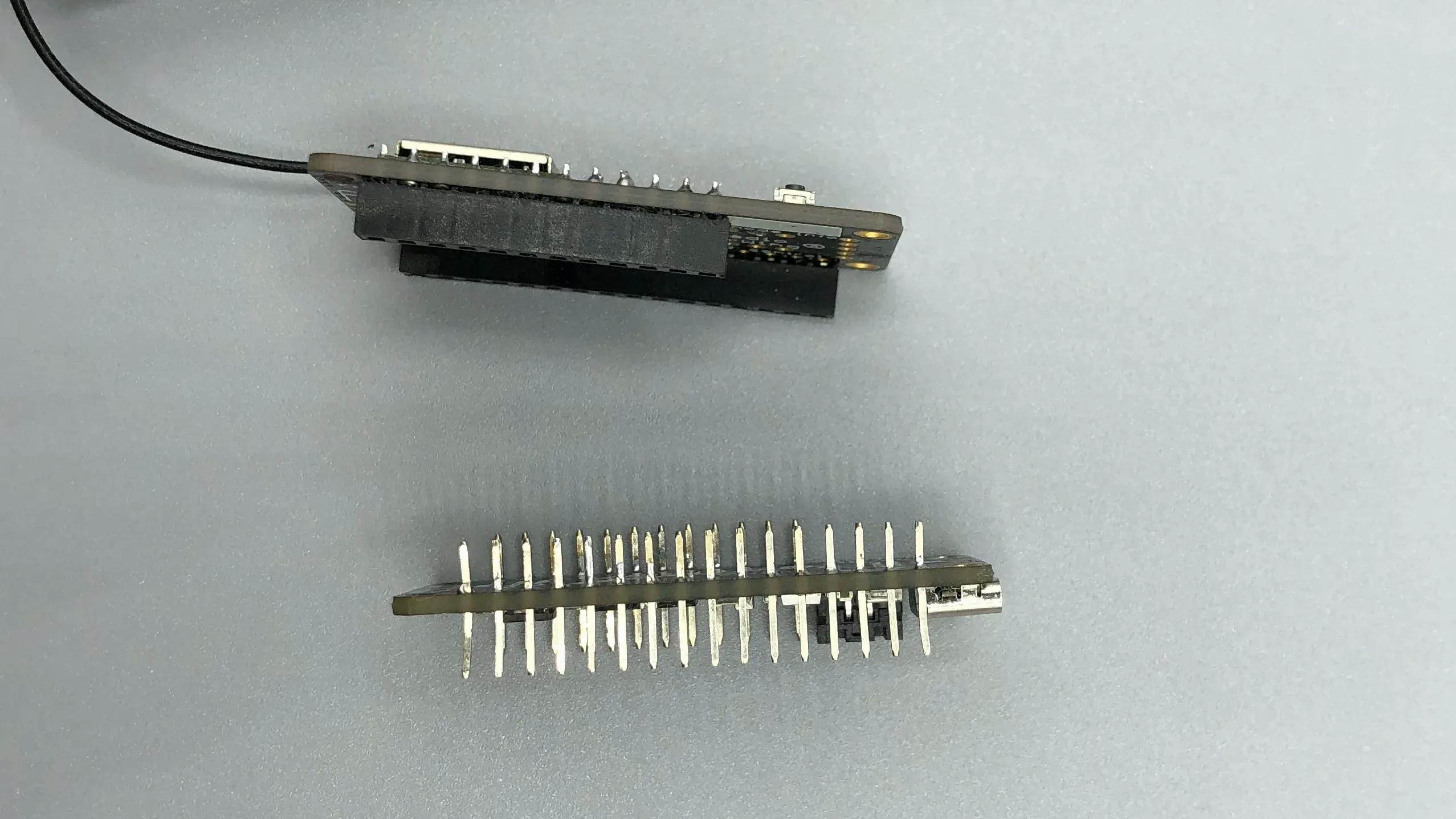
- Solder a set of pins to the M4 chip, exposing the full pin (remove the black plastics) that will allow the connections on both sides using the minimum space

Step 2
We need to connect a pin for the RST and CS pins (We could wire the IRQ, but it is not needed for the current setup). We are going to connect them to the D12 and D13 pins. Note that the code we use then maps it accordingly:
# Define pins connected to the chip, use these if wiring up the breakout according to the guide:
CS = digitalio.DigitalInOut(board.D13)
RESET = digitalio.DigitalInOut(board.D12)
After we are done soldering we can add the Antenna cable to the uFL connector.

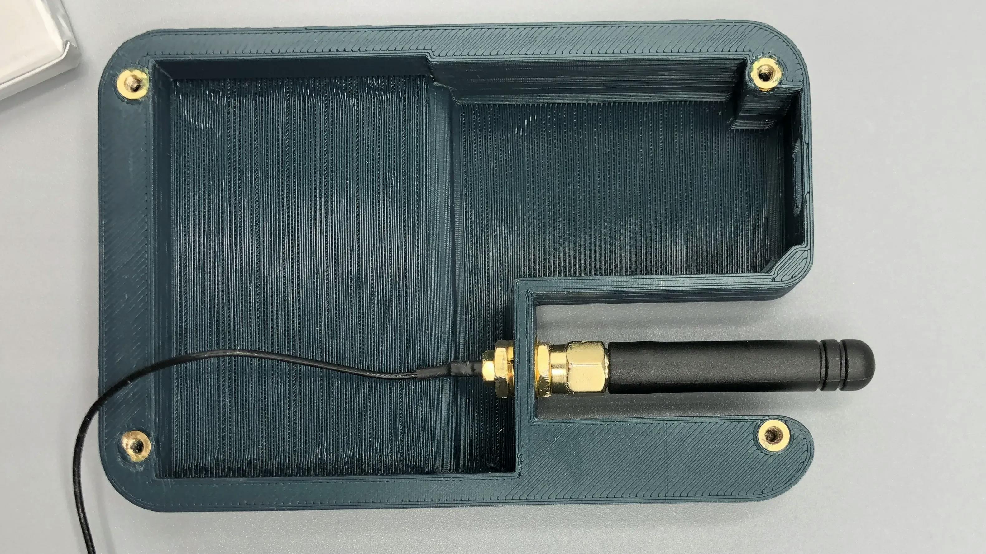
Step 3
We'll add the Heat inserts to the back plate. this is actually quite satisfying with the hakko setup.
Then we'll screw the antenna on the plate

Step 4 (OPTIONAL)
Depending on the polarity of your battery, you may need to flip it to match the Feather JST connector. The one I bought needed that.
Step 5
We prepare the “sandwich”:
1 ) Place the Front Panel face down on the working area
2 ) Place the FeatherWing Keyboard PCB on top of it
3) Add the Middle Panel
4) Connect M4 to the FeatherWing Keyboard
5) Connect the battery to the M4. Depending on the battery model you use, it may be a bit loose. In my case I added a furniture anti-slip patch I had laying around. That also help to absorb some of the shocks it may get.
6) Connect the LoRa chip to the M4
7) Add the back panel, make sure to wiggle it until everything closes and nothing is pinched
8) Place the screws on the front and tighten them up in an “X” in rounds, to ensure that everything is tightening up without force.
9) Add the lanyard to the top
Congratulations! you assembled the LoRa messenger!
The code can be found in the GitHub and the LoRa setup is well explained in the Adafruit website.
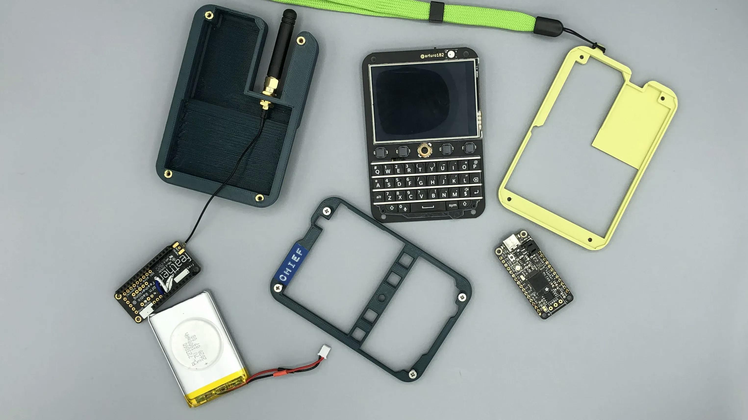
 Parts:
- 3d Printed Parts (stl files to download)
- Adafruit M4 Feather M4
- Lora FeatherWing
- M2.5 Heat Inserts
- uFL antenna connector
- Antenna
- Wrist Lanyard Strap
- Header Kit for Feather
- M2.5 12mm countersunk screws
- Battery - Be careful with the polarity, for some reason he one I bought from amazon had the opposite than what the FeatherWing expects. If you get that wrong you'll see some white smoke and that is rarely a good sign. I think that Adafruit sells them with the right polarity, so don't assume that it is right or it is wrong, test it.
- any header with enough pins for a feather
Tools:
- Solder setup (check the hardware page): solder iron, solder wire, reel stand, rosin paste, heat insert solder tips,
- 3D printer setup (again, check the hardware page)